So many reasons can be responsible for the broken camshaft. Reasons for a worn camshaft can be, among other things, low-quality engine oil or incorrect assembly (e.g. due to another previous repair).
Let’s dig deep to know what can cause the camshaft to break.
1. The camshaft has drawbacks regarding lubrication because it is one of the engine parts that lag far behind in receiving oil.
Consequently, if the oil pump pressure drops due to oil pump wear and tear, the oil passage hole designed for lubrication becomes blocked, or the bolt torque for the bearings’ journals or main bearings is improper, the oil won’t be able to reach the camshaft.
That will stop engine oil from getting inside the camshaft, which would otherwise cause the camshaft to wear out too quickly and fail.
2. As the camshaft ages, there will be an increase in the space between the bearing seat and the camshaft, which will cause axial displacement when the camshaft rotates and cause abnormal noise.
Strange noise and occasionally a damaged camshaft will result from the drive cam colliding with the hydraulic lifter due to abnormal wear, which will also cause the distance between the drive cam and the lifter.
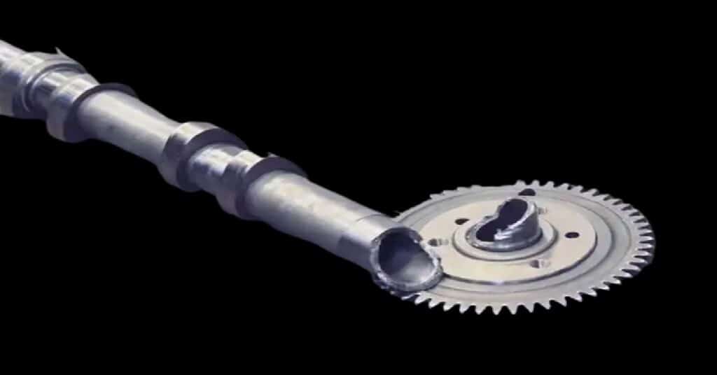
3. Common causes of severe failures, such as camshaft fracture, include excessive wear, damaged hydraulic tappets, insufficient lubrication, poor camshaft quality, and cracked camshaft timing gears.
4. Sometimes, human error results in the camshaft braking, especially after an engine repair. The camshaft is not properly taken apart and put back together.
For instance, installing the bearing cap in the incorrect location, which results in the bearing cap not matching the bearing seat, or tightening the bearing cap attaching bolt with too much torque are all examples of ways to damage the camshaft bearing cap.
Do well to use the appropriate tighten tool Use to tighten the bearing cover attaching bolts in exact compliance with the stated torque.
When installing the bearing cover, pay close attention to the direction arrows and position numbers on the bearing cover’s surface.
Do All Engines Have Camshaft
The camshaft plays a vital role in an internal combustion engine. For the opening and closing of engine valves to be possible, a camshaft plays its major role.
It is the major component of the valve train system. All other components that comprise the valve train system rely on the camshaft.
But does all engine use camshaft? The answer is no. 95% of engines use a camshaft, but some manufacturers have a means of designing engines without a camshaft.
For example, the opposed-piston engine has no camshaft because of the lack of a Valve train system. An opposed-piston engine is a diesel engine usually found in heavy-duty mechanical equipment.
However, some gasoline engines too can work without a camshaft.
How Much Power Do Camshafts Add To The Engine?
Sports camshafts are “sharper”, so they have a larger opening time frame and thus better filling of the cylinder if everything else is correct.
Cams that open 20° longer (i.e. 10° earlier opening and 10° later closing) than the standard parts bring a significant increase in performance.
It is 10-20% and always takes place in the upper-speed range. Since the maximum power is shifted to higher speeds when the valve timing is extended, you should check whether regions are reached that the engine can no longer mechanically cope with.
Robust series engines with low litter output and speed-resistant cam drive can also tolerate 30° or even 40° more opening, while mechanically exhausted high-performance engines, which rush into the rev limiter with 98% of the maximum torque, do not even allow 5°.
In such engines, which are at the limit in terms of the duration of the opening,
Even if your main concern is more torque, you should have a camshaft with the same or shorter valve timing but an increased stroke.
However, it may also slightly increase the performance in the upper-speed range.
Such a profile puts a much higher load on the valve train. But I know engines such as cams work well with the standard valve springs.
If the engine should only have power in the lower and middle-speed range, you can significantly shorten the control times and the stroke.
Add a smaller carburettor, and the engine will pull like an ox from below. When turning, however, it will quickly run out of air.
Some companies specialize in making camshafts. If you do not yet have any empirical values for an engine, you should clarify with these people what is possible and useful.
They don’t do anything else all day, and now they know what they’re doing. Tell them what you intend to do with your engine, and they’ll find something suitable.
I have had good experiences with the companies Campro and Schrick, but there are also well-known others (Megacycle, Großewächter, etc.).
The quickest and least expensive method to create a sharp camshaft is to re-grind a production camshaft.
Here the base circle is removed so that there is enough “meat” on the nock to be able to rework the profile.
Since this measure increases the surface pressure and requires considerable valve clearance adjustment, it is almost only an option for robustly constructed engines with valve clearance adjustment screws.
The valve seat could also be milled deeper, but this reduces the preload on the valve springs (which can be compensated for by placing the lower valve spring plates underneath), and the combustion chamber has to be reworked in the intake area.
Another good option, though expensive, is to apply the material to the cam before grinding it or installing a specially made camshaft.
The modified camshafts should be adjusted the same way as the standard parts. So overlap at or shortly before TDC, turn the camshafts a bit outwards, sometimes a little inwards and of course, always check the valves for sufficient freedom of movement.
Since a strong overlap of the valves at TDC worsens the exhaust gas values, it is usually relatively small in series engines.
In many cases, more overlap also improves mid-range performance. So it may well be that a sharp cam with moderately longer opening times and significantly higher overlap achieves a higher peak power. Still, the power in the middle range increases or stays the same.
But you will always lose something in the lower speed range.
So if you have a cam with 20° more opening, you should try to use only 5° for the later intake end or earlier exhaust start, but 15° for the overlap.
And if you’re having a sharper camshaft made for an engine with low overlap, consider whether you’ll need some of the opening time for the overlap. (Of course, the longer opening hours will also increase the overlap.)
A guide: The overlap height in racing engines is around 40% of the maximum cam lift.
The strong overlap, in particular, is limited by the freedom of movement of the valves to the piston crown (inlet 1.5mm/outlet 1.0mm) and to each other.
Before making an overly optimistic camshaft, you should check how much air is left or can be created.
In engines with a high bore/stroke ratio, the combustion chambers are very flat by design to achieve high compression.
As a result, the distance between the valves and the piston crown is very small, and you will almost always have to set the valve pockets deeper.
Since the valve train is often the criterion that limits the speed, there is the possibility of creating scope for higher speeds by reducing weight.
These can be lighter valves, tappets and spring plates. You can have these parts made out of titanium.
But titanium is not only extremely expensive and difficult to work with, but it also has terrifyingly poor friction coefficients, which is why the surfaces must be coated.
In engines with long pushrods, the problem is often less weight than the instability of the pushrods.
Since the valve springs are also part of the accelerated masses with about half their weight, you should see whether there aren’t lighter examples with the same spring rate.
Stronger valve springs should be a last resort. With sharper camshafts, longer opening times and unchanged lift, the cam has more time to open and close the valves.
It reduces the valve acceleration, and the possible speed increases.
The acceleration of the valves could therefore remain the same even with a larger valve lift and longer control times.
Increasing the valve lift compresses the valve spring more, so installing a slightly weaker spring is sometimes even recommended.
As a rough guide, you can calculate that a cam that opens 20° longer, with 1mm more lift, has valve acceleration roughly equivalent to the series and has slightly higher speed stability due to the more compressed valve spring.
A stronger spring would only be required for cams with steep rises and falls or a sharp increase in engine speed.
Since a stronger spring involves higher material loads, you should always try to achieve your goal by lightening the valve train first.
Stronger valve springs and larger valve lift stress the cam tips at low engine speeds, so the idle speed should be increased. Install a slightly weaker spring.
As a rough guide, you can calculate that a cam that opens 20° longer, with 1mm more lift, has approximately the same valve acceleration as the series and has slightly higher speed stability due to the more compressed valve spring.
With rocker arms and rocker’s arms, widespread in the past (rocker’s arms are just becoming fashionable again), the radius of the lever’s contact surface can be increased by re-grinding, thereby changing the valve lift curve.
However, very few people do that now because the valve acceleration increases significantly, and the cam drive quickly becomes hammer work.
The valve lift in the intake is usually 25-30% of the valve disk diameter.
More than 30% does not increase performance because the port diameter required for this cannot be available, and the high valve acceleration unnecessarily restricts the possible speed.
If you want to do the math for your engine. Effective annular gap on the valve = valve diameter x pi x valve lift x 0.71. The 0.71 is pretty much the sine of 45° (0.7071067).
However, this factor is only an approximation and considers the angle at which the gas flow enters the combustion chamber at the valve.
For example, a 40 intake valve with a 12mm (30%) valve lifts 1070mm². A duct with a diameter of 36mm has a cross-section of 1017mm².
And then there is the good 27mm² that a 6mm valve stem has. 990mm² remain. In this case, the valve opening would be too large.
The relative stroke of the exhaust valve is often higher because the flow velocity is already highest at the beginning of the exhaust stroke, and the usually smaller and lighter exhaust valve enables stronger acceleration.
However, once you have found the valve timing that allows your engine to run with the desired performance characteristics, you can try again to achieve the maximum cam lift your valve train can handle properly. It will almost always be worth it.
CAMSHAFT SENSOR FUNCTION: OPERATING PRINCIPLE
Camshaft sensors have the task of defining the exact position of the crank mechanism together with the crankshaft sensor.
Thanks to the combination of both sensor signals, the engine control unit know when the first cylinder is at the top dead centre.
This information is required in three ways:
- In sequential injection, at the beginning of the injection,
- the actuation signal of the solenoid valve in the pump-nozzle injection system and
- for cylinder-selective knock control.
The camshaft sensor operates based on the Hall principle. On the camshaft, a ring gear is scanned.
The ring gear’s rotation alters the Hall voltage of the Hall IC in the sensor head. The changing voltage is sent to the control unit, where it is evaluated to determine the required data.
The function of the camshaft sensor
The camshaft sensor belongs to the family of Hall sensors. It consists of a semiconductor through which a small current flows and is mounted close to a metal ring gear fixed on the camshaft.
When the motor runs, its teeth move past the semiconductor, changing its magnetic field and thus the current.
This change is registered. However, this alone cannot determine the position of the camshaft. The trick is to omit teeth on the sprocket.
There is also the option of adding just a single tooth marking top dead centre (TDC) for cylinder one.
A camshaft sensor is a mostly cylindrical-looking component located outside the cylinder head.
There, the sensor has the task of recording the speed and the exact position of the camshaft. It is done by the sensor scanning a sprocket on the camshaft.
The onboard electronics require data for precise fuel injection. Only then is safe, effective and environmentally friendly combustion possible.
Therefore, the camshaft sensor’s smooth functioning is important in several respects.
The data is A camshaft sensor that helps the engine to know the correct position of the piston’s mechanism (positions of the pistons).
Necessary to calculate the ignition and injection timing.
The engine control unit knows from the sensor signals when the first cylinder is at the top dead centre and the subsequent logical activation of the cylinders.
All the symptoms you listed cannot ONLY be caused by a defective camshaft sensor!
Poor starting of the engine is usually the cause of a defective NWS!
But if your car has no problem starting the engine, the NWS should be fine.
The possible suspicion of a defective LMM based on the symptoms mentioned should be considered.