
Another name for an air brake system is a pneumatic brake system. A pneumatic brake system consists of a pressure generator (compressor), pressure regulator, compressed air tanks, compressed air lines, and diaphragm cylinders (brake cylinders).
In contrast to a hydraulic brake in a car, in a truck, the pedal force generated by the driver is transmitted to the brakes by the compressed air generated by the compressor and not by the brake fluid that is permanently in the system.
The driver’s foot force acts not directly on the power-transmitting medium but a brake valve.
The compressed air requested by the driver via the foot pedal flows through a line system to the individual wheels, where a membrane cylinder moves the friction linings. The driver controls the required braking force via the pedal travel.
If the pneumatic brake allows heavy vehicles to be braked safely and permanently without reducing the braking force (fading), this brake is unsuitable for permanent deceleration.
Because the service brake of a truck would also burn up and eventually fail if decelerated for a long time, the legislator prescribes an additional, independent brake system (third brake).
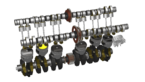
Directly pneumatically actuated disc brakes are used in practically all mechanical engineering sectors. The actuation force is generated here with compressed air; the brake is released with spring force.
The range of applications extends from light operations, e.g., B. for web tension controls, to high demands as a stop and service brake, for which braking forces up to 33,000 N can be achieved depending on the air pressure level with just one brake caliper.
Depending on the brake disc diameter and the number of brake calipers used, there are hardly any limits to the braking torque that can be generated!
What is a Dual Braking System
The braking system slows down the vehicle. It also allows you to stop or leave the car at a standstill. It affects the car engine, canceling or reducing the work it does.
To work correctly, a brake consists of four elements: the lever or pedal, the cable, the brake itself, and the moving parts usually attached to the wheel. Furthermore, we distinguish two types of brakes: drum and disc.
Now let us talk about the dual braking system. A combined braking system (CBS), also known as a linked braking system (LBS), is a system for connecting the front and rear brakes of a motorcycle, scooter, and moving equipment.
When one of the brake levers is pressed in this system, the driver applies both the front and rear brakes. A proportional control valve can determine the amount of each brake used. It differs from integrated brakes, where pressure on the rear brake pedal only applies a certain amount of braking force to the front brake.
For example, BMW Motorrad uses a system called Integral ABS, where the front brake lever operates both front and rear brakes, while the brake pedal operates only the rear brake. Conversely, the Honda system, which offers combined brakes and anti-lock braking systems, is considered combined ABS.
In this system, the rear brake pedal operates both front and rear brakes, and the front brake lever handles the front brake calipers, which activates a secondary master cylinder to use the rear brake. ABS modulators are present on both the Installed both front and rear wheel.
Honda’s first street motorcycle to feature a combined braking system (then called Unified Braking ) was the 1983 GL1100. This system is derived from a 1970s RCB1000 World Endurance Race Bike.
Honda has produced different variants of the LBS system with varying levels of complexity and integration.
The Honda CBR1000F and CBR1100XX, as well as the VFR800, featured what Hondadubbed LBS II (now Dual CBS), a system in which both levers operated both brakes via a system of secondary pistons and proportional/delay valves.
A front caliper is linked to a secondary master cylinder, and the caliper could rotate easily to apply pressure to the piston in this secondary master cylinder.
Braking force converted to pressure transferred to the rear brake cylinder. The brake lever directly actuated only the two outer pistons in the front calipers; the center piston received pressure from the rear pedal via the proportional – and delay valve.
The main difference between La CBS and Dual CBS Unlike Dual CBS, CBS operates with a single command, which can trigger a lever or a pedal.
HOW Combined Braking System (CBS) Works
The CBS braking system has a servo motor connected to the front wheel and an auxiliary master cylinder. The booster is responsible for delivering brake fluid from front to rear when braking.
Each caliper in the system has three pistons, a center piston, a front outer piston, and a rear outer piston.
The brake pedal is used to drive the center piston, and the brake lever is used to act on the outer piston of the front wheel. Finally, the servo motor pushes the outer piston of the rear wheel.
So, the center piston is pushed back and forth when the driver depresses the brake pedal. And when the motorcyclist presses the brake lever, the outer piston of the front wheel is pushed.
However, during harsh braking or sudden driver braking, the brake fluid activates the auxiliary master cylinder, causing the booster to push the outer piston of the rear wheel.
What are the Five Basic Components of an Air Brake System?
The braking system of heavy vehicles is pneumatic, therefore using compressed air. The pneumatic system is made up of valves that, according to their functionality, allow a proper conveyance of the compressed air and, therefore, the vehicle’s braking.
Let me tell you five essential components of an air brake system.
1. Compressors: The compressor is the heartbeat of the pneumatic braking system. The pneumatic compressed air compressor is indispensable for correctly functioning truck braking.
During the regeneration phase, the pistons, the valve, and the gasket kit are replaced.
At the closing of the assembly phase, the compressor is placed on the appropriate test bench and subjected to a stress test. The test bench allows simulating the compressor’s operation to evaluate its functionality and reliability in conditions of minimum and maximum tightness.
2. Air Storage Tanks: Compressed air is stored in storage tanks. Vehicles differ in the number and size of their air tanks. Even if the compressor fails, the tanks will still contain enough air to allow the brakes to be applied numerous times.
3. The Brake Pedal: By depressing the brake pedal, you can apply the brakes. The foot valve is another name for it. More air pressure is used when the pedal is depressed more firmly. The air pressure is reduced, and the brakes are released when the brake pedal is released.
When the brakes are released, some compressed air exits the system, lowering the pressure of the air in the tanks. The air compressor needs to compensate.
Unnecessary pedal pressing and releasing can cause air to escape quicker than the compressor can replenish it. The brakes won’t function if the pressure drops too low.
4. Brake Shoes and Drums: By using friction, the brake shoes – or pads, depending on the make and model of the truck – are forced outwards, thus initiating the air brake system. A special brake lining material is attached to the brake shoes to help promote consistency.
If the type of lining is a good fit, it should also regulate the heat created from the friction.
How Brake Work in Train
Many overlook the train’s speed and pay little attention to its weight and, consequently, its braking distance. A train passing through, i.e., not stopping at a stop or station, can reach a speed of up to 140 km/h.
In contrast to a car, whose weight does not exceed 3.5 tons, a train carrying passengers in a maximum of 16 vehicles weighs up to several hundred tons. Thus, a passenger train needs up to 1,200 meters to stop, which is 13 times the length of a standard soccer field.
The braking system, which must be as powerful as possible for a rolling stock that carries thousands of passengers daily, varies depending on the type or series of trains.
Not all locomotives travel at a similar speed, with the same mass or length. Let us consider three fundamental different braking systems in train:
- Pneumatic braking: This braking device helps to control passenger trains and works perfectly thanks to compressed air that circulates in the braking circuit and actuates the brake cylinders.
A so-called ‘air main,’ with air supply via the railcar, runs inside the train and its carriages to ensure vehicle continuity and control the train’s brakes. In other words, this main air pipe feeds the air tanks of each car so that each has the air reserve necessary for braking.
Applying the brakes causes a pressure drop in this air-filled leading airline. A reduction in the pressure in the main airline, therefore, causes the air to escape from the surge tank via the distribution device installed on each vehicle towards the brake cylinders.
The air supply to the brake cylinders leads to the pressure of the brake pads or soles on the wheels or brake discs. It should be noted that braking force is proportional to the air pressure stored in the brake cylinder.
This type of braking is also known as “automatic braking” because a loss of pressure in the main brake pipe results in the automatic application of braking force to all vehicles in the train, for example, when a driver applies the emergency brake.
2. Electric braking: Another name for it is regenerative braking. The so-called “regenerative or regenerative braking” system uses the engine as a power generator. The mechanical energy (produced by the movement of the train) is converted into electricity and fed back into the catenary.
When braking, the induced counter-resistance causes the train to slow down without mechanical brakes. In other words, the electric brake efficiently manages all the key mechanical elements, such as the axle and braking units.
Because it is taken over by the traction system depending on the train’s speed, this braking device is automated and, through regeneration, completes the pneumatic (mechanical) braking system.
This type of brake is found on board all CFL railcars and locomotives (2000, 2200, 2300, 3000 & 4000 series).
Finally, the electric braking system has various advantages, such as saving electric energy thanks to regeneration. The brakes are also protected against wear and tear, which helps to minimize the time the rolling stock is held in the workshop and thus optimize its availability.
- Electromagnetic braking: Electromagnetic braking is a device that does not rely on wheel-rail contact and whose braking action is applied directly to the track. In other words, a magnetic contact shoe attached under the chassis in the wheelbase touches the rail.
The train is held back thanks to the friction of the contact shoes, which are pressed together by magnetic attraction. In addition to a mechanical device of the pneumatic variety, magnetic braking is principally used in the event of emergency braking, which is referred to as emergency braking.
These are the three major braking systems in the train. Although some train models have other brake systems, the braking mentioned above is the major one.